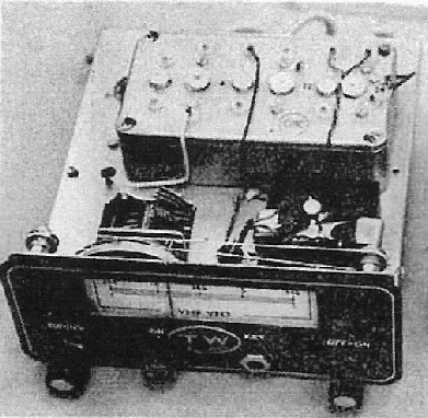
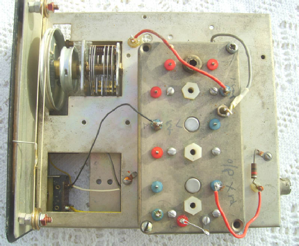
Up to November 2013, the photo above was the only photo of the TW solid state VFO for 2m that was available and had been scanned from an article in the RSGB Bulletin Dec 1965 (courtesy of the R.S.G.B). The unit was unconditionally stable and was based on a circuit known as 'The Synthetic Rock'. Output from the oscillator (running at around 6MHz) was very low and was boosted by a couple of stages of amplification and was then multiplied to 24MHz and used OC170 transistors. It was intended for use with any 2m transmitter using 6, 8, 12 or 24Mhz crystals and could be plugged directly into the crystal socket (with for example a TW2 transmitter) and stability was such that it remained at zero beat for hour after hour when monitored on a TW Twomobile receiver. It gave the full range of 144 - 146MHz with a constant output over the range and there was a CW facility which produced a clean T9 note with no drift. The chassis and case of the TW mobile receiver was employed in its construction (dimensions of the unit 6in wide, 7in deep and just under 3in high). According to Tom, "the intention was to use a built in power supply, but despite our best efforts it was impossible to eliminate ripple from the output waveform". The VFO was designed and manufactured at the Gilbert Street works.
There were plans to develop a version for use on 4m, to be available in 1966. However it is not certain that any were ever produced.
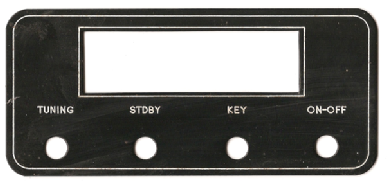
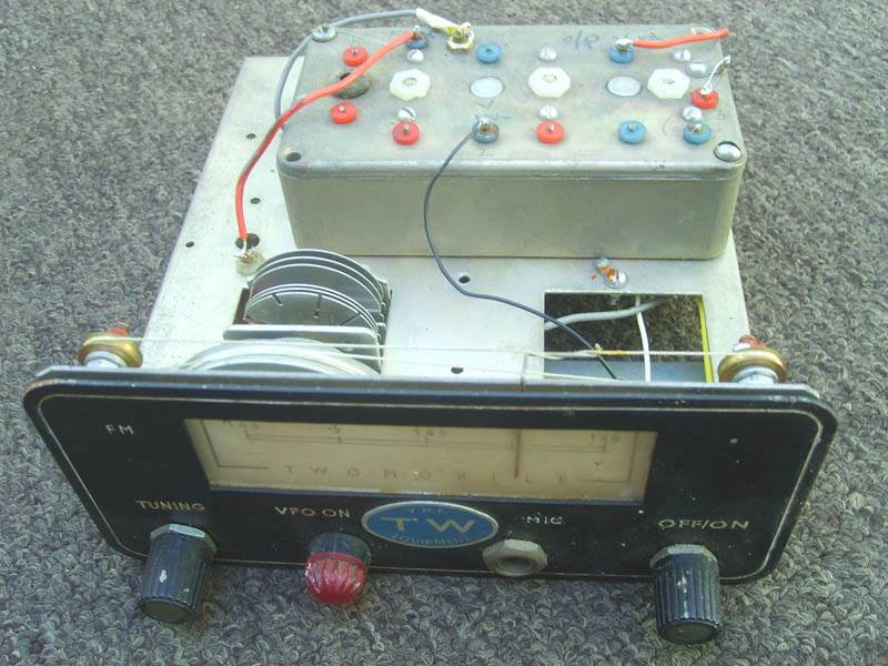
The front plate (Tom Withers still has one) is shown to the left.
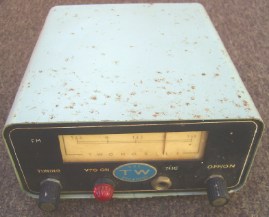
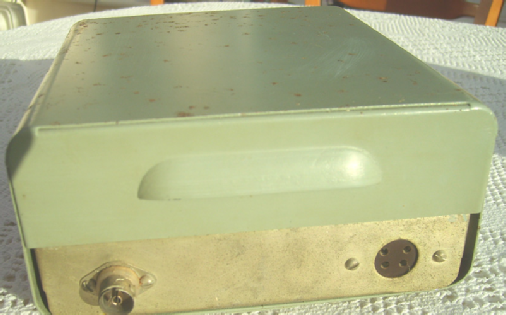
I know from Tom that not many of these units were built, so I consider myself extremely lucky to have obtained one in late October 2013. The case of the unit is showing some surface rust on the top and one side (as may be seen in the photos) but this will be fairly straight forward to remove (he said hopefully) and the case will then get the same treatment as I applied to my TW Communicator PSU.
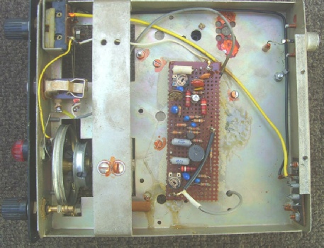
The inside of the VFO is in fantastic condition considering the age of the unit, however it has been modified at some stage. The veroboard underneath the chassis is not original. I believe it is an audio stage to 'FM' the VFO (an 'FM' label has been added to the front panel and where it says 'MIC' on the front panel, it should say 'KEY'). Comparing the poor scanned photo with this unit, it would appear that something may been removed (from above where the rectangular hole in the chassis is) but I don't know what as I have no circuit diagram. Tom may be able to shed some light on it, but it's been a long time since he built these units.
The front panel may be more difficult to 'tidy up' as some of the 'writing' is rather worn (and modified !).
 Home
Introduction
History
Equipment
Circuit Diagrams
Operating Instructions
Credits
Leaflets
Website changes
Miscellaneous
Photographs
Home
Introduction
History
Equipment
Circuit Diagrams
Operating Instructions
Credits
Leaflets
Website changes
Miscellaneous
Photographs