 Home
Introduction
History
Equipment
Circuit Diagrams
Home
Introduction
History
Equipment
Circuit Diagrams
TW Electronics 1958 -
TW Nuvistor Converters
These converters used the RCA 6CW4 miniature nuvistor which had a remarkably good low noise performance and this unit replaced the Cascode converter previously produced by TW. The nuvistor converters had approximately 30dB gain and 70dB I.F. rejection.
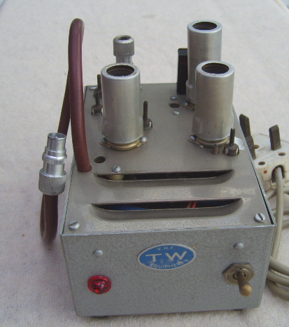
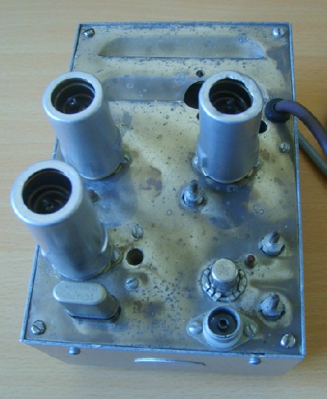
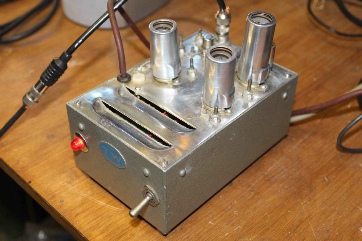
The photographs above show a TW 2m nuvistor converter, this particular one having its own built in power supply (which retailed at £15), but they were also supplied without a built in P.S.U. (which retailed at 11 gns.). For those of you too young to remember, a guinea was £1 and 1 shilling, equivalent to £1:05 in today's currency. These converters were available with a choice of I.F.s (e.g. 28-
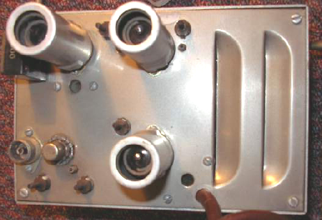
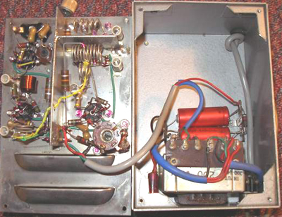
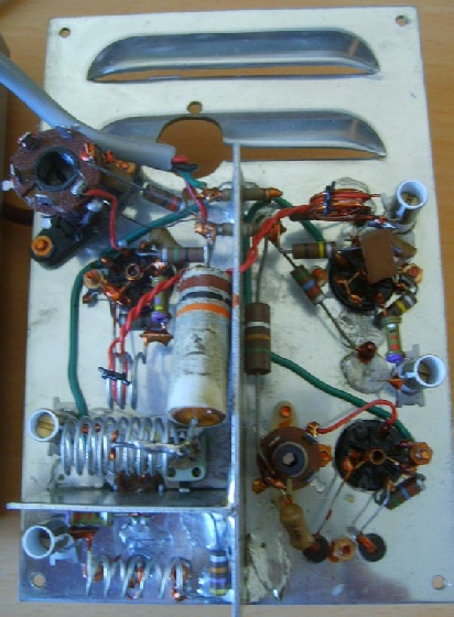
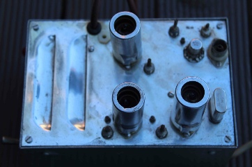
The photograph above left shows the 'innards' of the converter with all the components mounted on the lid and the P.S.U mounted in the box. The nuvistor can be clearly seen on the photograph above right (just to the right of the Belling Lee antenna socket). My thanks to Howarth GW3TMP for the converter and the original photographs.
According to an advert from 1964, a 4m version was also available (again with a choice of I.F.s) .
Vern M0WQR has kindly sent in some photographs of a TW nuvistor converter that he acquired at a rally (May 2011) for the princely sum of £2.
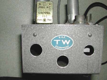
As may be seen from the photograph alongside, this particular unit seems to have gained some extra ventilation and is missing the on/off switch and the indicator lamp.
I am not altogether sure what I.F. this unit is using, the marked crystal frequency being 7680kc/s.
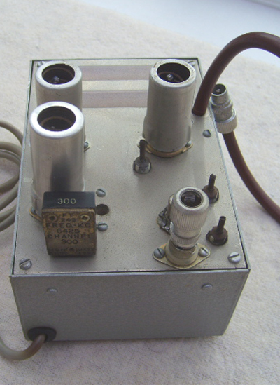
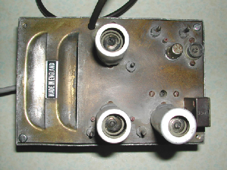
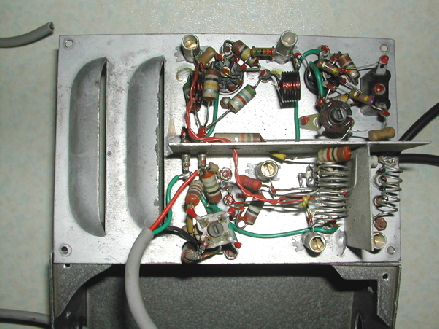
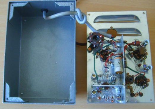
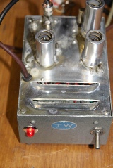
I recently acquired another 2m TW nuvistor converter but this one does not have a built in power supply (photos below).
This particular unit uses a 28 -
In September 2017, a friend of mine overheard a conversation on 80m in which mention was made that an item of TW equipment had been seen at a recent event held at Finningley Amateur Radio Society near Doncaster. I emailed the club and promptly received a reply from Martin M0HOM who confirmed that the club had a piece of TW equipment that had been donated to the club through a SK. From his description it seemed likely that it was a TW converter and this was confirmed when Martin sent me a photograph.
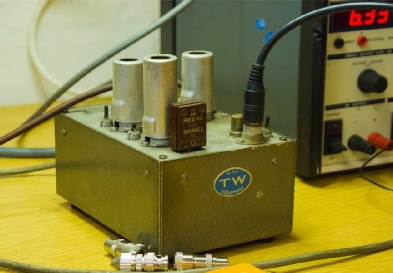
The unit is a TW nuvistor converter for the 2m band. The FT243 crystal is marked as 6450 kc (6.45MHz) meaning that the converter is intended for use with a receiver tuning approximately 28 -
According to Martin, the converter was given some ‘volts’ and after checking the heater current being drawn HT was applied with no apparent problems. After a mad search for Belling Lee connector converters, a 2m antenna and a suitable receiver were connected and the TW2 was successfully converting again! Magic !!!
Martin went on to say that when listening to GB3VHF using his Yaesu FT-
FARS are proud to be able to display it in their museum, and think that it is fantastic to have the option to actually use it, and not just look at it.
Photograph above provided by Martin M0HOM and used courtesy of Finningley Amateur Radio Society (FARS).
Julian G8HCZ has kindly sent in some photographs of a TW nuvistor converter that he recently acquired.
Julian comments:-
It is as suspected a 4m converter and I have been able to get some beacons on 4 plus my own small signal source (no actual amateur signals though as there is nothing round here!)
Basically its quite reasonable, a bit noisy, as one might expect, but when you get the front end neutralisation sorted out it is not too bad. Its an ‘S’ point down on my PW Meon transverter for the same noise level, but good for the 1960s!
The oscillator doesn't have stabilised HT, so consequently it moves up and down as the mains voltage changes. The LT is a bit high -
I had to replace a couple of caps and solder some wires which had come loose. I had an EF95 and a 6J6 in my junk box. I aligned it and set up the neutralisation on the front end and I have just cleaned up the chassis with ‘brasso’ and ‘meths’ and polished up the crystal and screening cans and it looks quite nice now. Sounds good too on a continuous tone. It does have a bit of AM breakthrough from the 10 MHz if -
This converter has a 10 MHz IF. The local oscillator is at 60 MHz, provided by a 36 MHz crystal in 5th rather than 3rd overtone. The actual frequency is 59.9958 so its a little bit off. I have another spare 36 MHz crystal and tried this but its almost the same frequency, so I think the calibration was never exact. It would be fine using a receiver with an analogue readout (like an EC10 or 9R59Ds).
The valve lineup is 6CW4 (RF), EF95 (Mixer), 6J6 (5th OT oscillator), EF95 (amp). The output to the Rx is via an untuned transformer, so it would have been easy to change the IF. I imagine that in production they would be set up with a standard IF and then the crystal would be changed on order to give the required IF.
Julian also took the trouble to sketch out a circuit diagram for the converter -